
Compensator Design · Lesson
English translation
Execution conditions
MATLAB · Control System Toolbox
Topics covered
Decide whether to adjust lead or lag compensation when speed, damping, and steady-state error must be met together.
Overall workflow
Performance targets → compensator poles and zeros → closed-loop response → compare speed and error
Defining the compensator's role
Add poles and zeros when a single gain cannot meet response-speed, damping, and steady-state-error targets together. First define the desired performance numerically with units, then choose a compensator type.
Distinguishing design from validation
Lead compensation mainly adjusts phase and speed; lag compensation mainly adjusts low-frequency gain and steady-state error. Even if the design point is met, input cost or other poles may cause problems.
Examine the compensated and uncompensated responses using the same step and ramp conditions and sufficiently long recording intervals.
Lead compensation with the same DC gain
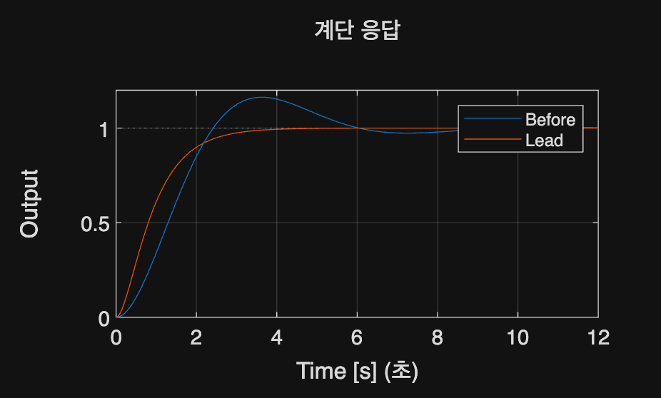
Compare G(s)=1/(s(s+1)) and C(s)=(s+1)/(0.2s+1). Examine how the response shape changes while keeping C's DC gain at 1.
%% Worked example
s=tf('s'); G=1/(s*(s+1)); C=(s+1)/(.2*s+1); t=linspace(0,12,1201)';
figure; step(feedback(G,1),feedback(C*G,1),t); legend('Before','Lead');
xlabel('Time [s]'); ylabel('Output'); grid on; disp(dcgain(C));
Reference example
View more examples